|
With the main sections of the fuselage rear
sections now made, as well as the bulkheads, it was time for Howard
to move on to making the side and top and bottom sections for the rest of the
fuselage. Each section was meticulously pieced together. Folks have
asked Howard "How many feet of precut plastic strip went to this 1/48
Wellington?".....Howard knows the answer...."140 feet" (45
meters).
Howard had to create the cockpit sections of the
fuselage framework next. This section of the plane involves many bulkheads....all of
which are unique.
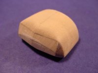
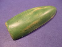
| To the right
is the wooden master for the cockpit canopy. The clear canopy was
made using this master. |
|
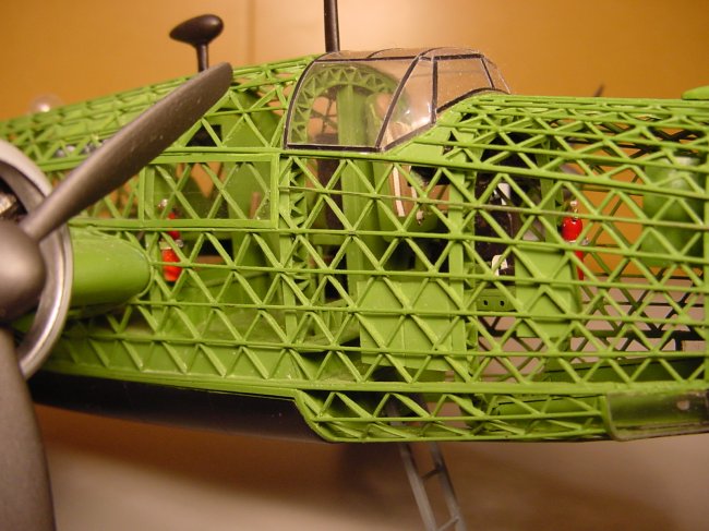
As you can see in this
picture, there are 2
bulkheads that have doorways in them to permit the nose gunner and pilot to more
to the navigator's section of the plane. In the above picture you can see
2 fire extinguishers painted red. Howard had to paint these red
and glue them to the green bulkheads and assemble the various sections of
the fuselage together to create the fuselage. Then Howard had to
airbrush more green to touch up the joints where there wasn't any paint.
This required him to apply wet tissue paper through the assembled frame
work to cover the red
fire extinguishers before he could do his final green painting.
|
| Click
on image below to see larger image. |
 |
|
Once all the diagonal pieces of
the geodetic frame work were assembled and glued together....then the outer
horizontal pieces of the frame work were added. These gave the structure
much more strength on the real plane. On this model, these horizontal
framework pieces gave the model the ability to hold itself together, but the
model is as delicate as it looks and isn't touched in any way by anyone except
Howard.
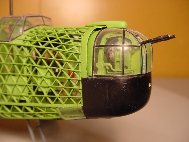
Nose Turret
The nose turret was created at this point.
This whole assembly is fully functioning. After it was built it was
carefully stored away to the very end when it would be added.
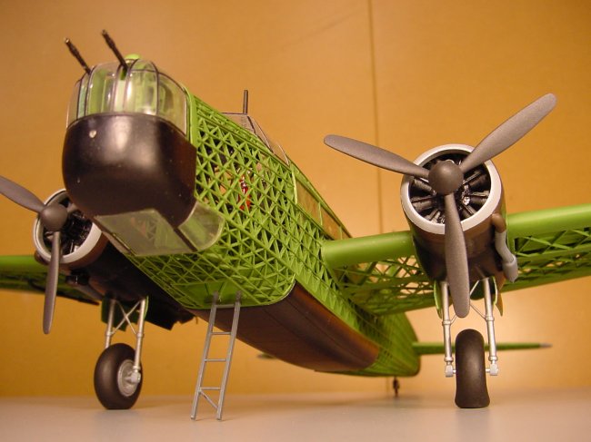
| In this picture you can
see some of the tiny detail that was created to make this fully
functioning nose turret, including some metal parts that would provide
longer life for the moving parts. |
|
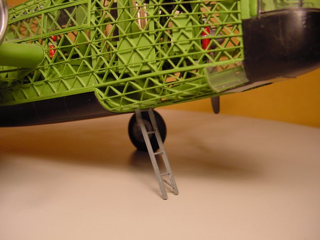
| Here you can see
the underside of the nose including the bomb bay doors further back.
Also in this picture is the crew access ladder as well as a
good view of the main landing gear. |
| Click on
image below to see larger image. |
 |
|
Engines
|
The engines were all scratch built.
The cowlings were made by creating a wooden master and then vacuforming
pieces from that. To the right is one of the wooden masters used
to create the engines cowlings.
|
|
| It the top picture to the
right you can see the completed engine cowlings......not a simple shape
to them. In fact the cowlings were made from many pieces of
plastic that were all formed to the correct shape before all of them
were joined together to get the finished look and shape of the engine
cowlings.
The actual engines themselves were
scratch built with all the outward appearance and detail of the real
engines. |
| Click on
images below to see larger images. |
 |
 |
|
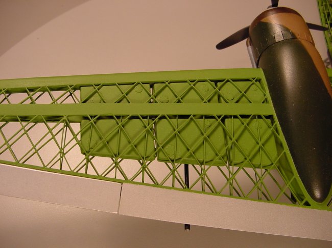
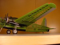
The 3 pictures below show the
wing structure from different angles. You can also see the wing fuel
tanks. When completed, this model has quite the surprisingly large
size. The fact the wings can be supported at the wingroot is a testament
to Howard's careful planning and workmanship.
| Click
on images below to see larger images. |
 |
 |
 |
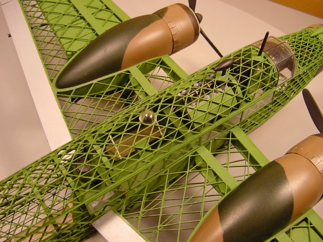
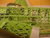
The picture below shows the wing root area quite
well. This is one of the sweetest pictures I took of Howard's
Wellington. Notice all the detail inside. This model is very scary
if you consider the effort involved to make something like this. When he
lifts this model he uses slings that go under the fuselage front and
rear....much like moving a Killer Whale. Needless to say, when he's moving
this model.....everyone stands "way the heck back" to avoid being
anywhere near the model if it should fall or be damaged. This model is
seldom taken out of Howard's home due to it's very delicate nature.
|
Howard needs
some reference material assistance.
Currently,
Howard is working on a 1/24
Skinless Sea Fury.
He's collected plenty of reference material, but he is stuck on 2
critical areas.
-
The
second area Howard needs info on is the hydraulic line system
throughout the entire plane. Basically Howard is looking for
any info on the placement of any and all hydraulic lines throughout
the entire plane. His 1/32 Sea Fury will have no skin, at all,
so all the details will be exposed.
Two ARC
regulars have sent in 2 articles for me to pass along to Howard.
One is the Sea Fury article from Scale Models International October 1983
and the other article is from "Scale Models" (unknown
date). Both of these articles have provided Howard with some badly
needed information and he is greatly appreciative to the 2 gentlemen
that sent these articles in.
What Howard
could really use now, is the factory manuals that show this sort of
detail....perhaps mechanics repair manuals? If someone has access
to such a book...... a few select photocopies of key pictures
would probably provide Howard with the detail he needs to complete his
Sea Fury.
Howard is an
older gent and doesn't own a computer......please send any e-mails or
info to Steve Bamford and I will
pass along the info to Howard.
Howard is
willing to pay a reasonable amount for this reference material.
Please
try to help.
I've
seen his partly built 1/32 Skinless Sea Fury....it is as cool as the
Wellington above.
Thanks!! |
| FEATURE |
FEATURE |
 |
 |
|
1/48 Skinless Scratch Built
Wellington bomber Part 1
|
1/48
Scratch Built Skinless Wellington model Part 3
|
|
by
Howard Hill
(no Internet connection)
|
by Howard
Hill
(no Internet connection
|
|