History
The
Gloster Gladiator was Britain’s ultimate Biplane Fighter design, giving he RAF
their first fighter capable of 250mph, four machine gun armament, and an
enclosed Cockpit. Serving first in the period when the RAF was waiting for their
first monoplane fighters, the Spitfires and Hurricanes, the Gladiator soldiered
on for the duration of the conflict in various duties.
The
Gladiator served valiantly in France, Norway, the Mediterranean, and Middle
East, and with the Fleet Air Arm.
RAF
Gladiators alone downing some 300 enemy aircraft.
The Model
Some
10 or more years ago, I picked up 5 “Life Like” 1/48 scale Biplane kits in a
variety store at clearance prices. Having recently completed the Fairey
Flycatcher, I decided to embark upon construction of the Gladiator after
finishing a couple of FW190’s
Packaged
in a colorful box, the mouldings still stand up well and generally fit was good.
Ejection pin marks however took a couple of sessions to fill and smooth
out.
Non
of my references gave much in the way of interior frameworks, so a psuedo frame
was laid in on the fuselage sides using suitably sized plastic rod to take away
the blankness.
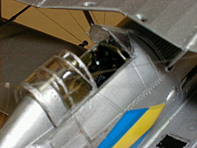
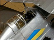
Utilizing
pictures from the IPMS Stockholm net site, an instrument panel was fabricated
and painted a reddish brown to match what appeared to be a Bakelite Instrument
panel in the preserved Machine in Sweden. The scrap box donated a brass
seat and seat belts, which were installed, brass rudder pedals and a plastic rod
gun site tubular frame and gunsight, along with a
spade tip Control column, were also fabricated and installed.
All
holes for rigging wires were drilled at this time using a fine bit in a pin
vise.
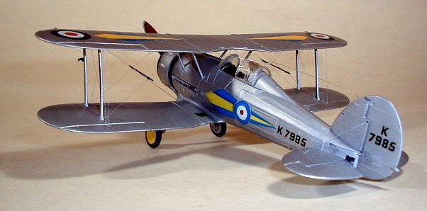
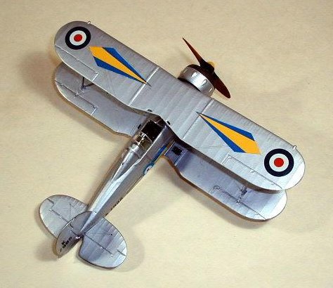
Thin
plastic strips were fabricated to replicate the
sealing strips over where the wing fastened
to the fuselage and upper wing centre section, seen as white strips at
the wing roots in the picture.
| Click on images below to
see larger images |
 |
 |
 |
For
Biplanes, I like to assemble the fuselage, lower wing etc.,
and paint, including the underside of the top wing, before complete
assembly. Carefully masking, or Blue Tacking the mounting pins, holes, etc. to
protect from paint and provide a better glue joint later
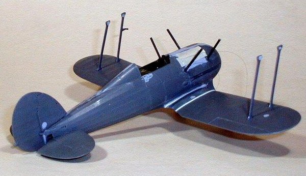
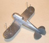
This
assembly was painted with Floquil “Old Silver”, Looking carefully at this
picture, it will be seen that the Cabane stuts have disappeared, I knocked them
off several times and finally removed them and drilled holes in the proper
locations, fabricated new struts from plastic rod, about ˝ inch too long,
painted and just slid them into the holes without gluing at this time.
| Click on images below to
see larger images |
 |
 |
 |
Working
up side down, the Upper Wing was glued to the outer wing struts and left to dry,
later the cabane struts were slid out of the fuselage holes and super glued to
the wing. When these joints were dry, some super glue was run around the
fuselage/cabane joint. It worked!
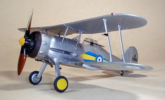
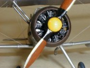
While
the Kit Engine is really quite good on it’s own, plastic rod ( I have never
mastered the fine art of stretching sprue) push rods were added, copper ignition
wires, and Carburetor air intake tubes were also added.
Since
the engine and Cowl could be added as a separate module, these items were
painted and assembled as a unit. Three “V” shaped cowling braces were made
from rod and installed from the Crankcase to the inside of the cowling.
Not
having had much luck with drilling out the exhaust pipes, short lengths of
tubing were added to the slightly shortened exhausts, blended in with putty, and
sanded smooth. The tips of the tubing were thinned to scale using a miniature
rat tailed file.
All
components now being assemble and painted, the rigging
was added through the previously drilled holes and anchored with super
glue, which also filled the rigging holes. These were carefully sanded smooth
and the paint touched up, the Floquil silver touched up beautifully, completely
hiding the rigging holes.
The
antennas, which were the last items to be installed were made from
“invisible” nylon thread from the local Sewing Store, via my Wife’s Sewing
Box.
Decal
Time. The fuselage side Decals went on fine, as did the serial numbers, and
lower roundels, however, the upper wing markings disintegrated in the soaking
process. Calling around to friends, I obtained another set of Decals from friend
Jim Mac Kenzie in Ottawa, I was no doing fine until I started to place the upper
Wing decals, once again the Modelling Gods smote me and the wing decals
disintegrated.
(
I think the Moral here is to coat old Decal sheets with a coating of Microscale
“Superfilm”, I now have a bottle on hand!)
A
sheet of Frisket paper was purchased and after a couple of tries, a good set of
spray masks were cut out for the
upper wing “diamonds”, The Yellow was sprayed on first, in order to spay the
Blue, a second mask had been prepared, the first Frisket mask
was removed, which carried away the paint and part of the wing roundel.
My goodness said I!
After
wet sanding the paint on the upper wing, and sanding off the remainder of the
roundels, the wing was resprayed and left to dry for over a week.
Now
I did what I should have done in the first place, cut masks out of Tamiya Tape
and sprayed my colours. No problem.
(I
have since had a little better luck with Frisket paper)
The
final step was to install the nylon thread antenna and shrink it, along with the
rigging to tension the thread. This was done by lighting a match, blowing it
out, and passing near the rigging threads, being very careful not to touch the
thread with the match, several matches later, it was done.
The
brave of heart might try a hair dryer, but not I.
These
Kits have been re-issued several times under various labels, such as Pyro and
Lindbergh, build into a nice Model, and can still be found.
References
Andy
|