|
“The
Hovering Harrier”.
The aircraft itself
is already famous, so I don’t want to drill down into historical and
specification which you guys could find in many websites. This Hasegawa kit has
been available for long time so it’s not new and comes with Hasegawa trade
mark of an accurate and quality material. What makes it a bit different from the
others basically is the pose that I made for this kit. After thinking for quite
sometimes and looking for ideas it struck me. The Harriers best feature is the
ability to hover, but so far no kit or aftermarket resin or mods provide
this pose. Rather than a normal pose of sitting on the ground or the flying pose, I
chose to set the kit into the hovering pose, which is the best feature of the Harrier.
Research
To do so, I’ve
done lot’s of research from reference books, magazines, and photos from
websites also from the Harrier video. Searching if anyone has done this pose
with some instructions on how to do it. I found minimal information on this.
One
of the key challenges is to pose the flaps in the lowered position. Photos
in books and websites do not show details, especially on how it moves and how the
mechanics on the flaps operate. With this photo and some other references showing the
lowered flaps and with some guessing. I embarked with this project.
Click on
images below to see larger images
|
|
|
|
|

|
|
|
|
Photo 3 |
|
Photo 4 |
|
Photo 5 |
|
Photo 6 |
Construction
For more details of
the mods made during the project, you could find in the “Project” section of
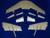
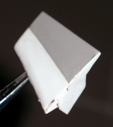
my website (it’s in Bahasa Indonesia). I started with cutting all the
flaps and aileron. I did this while it’s unglued, so it needs to be cut from
the upper and lower portion. See picture #3 above. Once cut, I reconstructed the whole
flap using styrene sheet (0.3 and 0.1), by looking at the photos trying to
imitate the figures, closing any gaps with styrene pieces and later on with some
putty. See picture
#4 showing the completed piece. It’s done for both side.
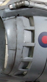
Another modification
is done to the air intake area on the additional air intake cover. In the kit
only the upper half which is slotted open, a usual condition for a static pose on
the ground (no air flowing). However when it’s hovering all the additional air
intake cover is fully open. This is quite a challenge with a little room to
play, I use the Hasegawa try tool to saw loose the remaining closed air intake
cover. Refer to picture #5 above, once it’s open, I then added styrene 0.1mm
sheet imitating the open cover. I did this for both sides.
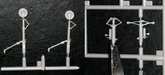
Actually after this
step I planned to move to normal construction steps. However observing the picture
another fact struck me, were all the undercarriage are hanging low due to
gravity. Thus all undercarriage pieces are longer in length. I decided to go all
the way, started with modifying the undercarriage pieces by adding a similar
size cylindrical plastics using heated unused sprues (stretched it to the
diameter similar to the shock absorber cylinder size). Cut it, glued it, doing it
several times until satisfy with the results. Picture #6 above shows the
difference before and after the mods (using the new pieces from the AV-8B II
kits). Don’t forget to cut and re-glue the retracting joints or just try
bending it (careful here or you end up with quite a mess).
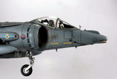
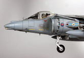
Once all the major
mods are done. I went to the normal construction steps. Which start with the
cockpit. Here I ended up with another major overhaul of the cockpit.
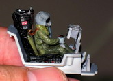
I saw the
ejection seat is the wrong version for the GR MK7 (it's supposed to be Martin Baker 12A). The
kit provides the ejection seat for AV-8B (Hasegawa you could have done better or
probably some version does have this one?). Rather than buying the resin version,
I already was in a rush to start the kit, I decided to DIY the seat by using the
unused ejection from the F-18 Hasegawa kit which to me much more resembled the
Martin Baker structure. As it will be posed with the canopy closed then the
details of the seat will not be noticeable enough from outside. The mods were done
on the head rest portion, reconstructed using styrene and some unused pieces
from other kits. (it’s not real but looked realistic enough to me). Painted
black, adding some decals to show similarity with the real photos, numbering of
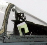
the seat is totally random but looked cool when finished. Refer to Picture #7.
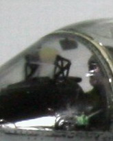
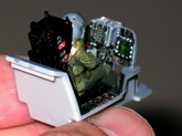
Another cockpit mod is done to the MFD/radar screen using reflective material
which looks astonishing (sparkling materials for wedding gown). The green hue
and reflection is dramatic like the real screen even when there is light it’s
also reflected to the helmet visor… wow. It’s not so apparent in the photos,
but you should try this. Adding details by replacing the HUD bracket with
aftermarket PE set (only use the HUD pieces, other are saved for open cockpit
pose, got two PE set, actually thinking of using the kit transparent, but the
Canopy is so huge and transparent all details are apparent. To be more realistic
in GR MK7, the pilot used to put a map or mission paper in the right side of the
instrument cover, so there it is, and another small reflective small sensor on
the left side was also re-created. For the pilot, I displaced the oxy hose to the
left side of the masker, and added the safety jacket (used by the harrier pilot)
using a tack glue (easier to mold) and paint it. Glued, painted with base coat,
details and such… the final one can be seen in several Picture #8, #9, #10.
After this cockpit
construction I followed the instructions for the rest of the kit, except for
gluing of the lowered
flap and aileron which is done after all body construction is completed. I
chose to glue it before it’s painted to have stronger bonding. One issue is
on the hot jet exhaust protection plate where it’s too thick. Thus I did some
grinding
to make it thin, so it can be attached last when all things have been painted
(this will be painted in rusty exhaust colors later on). Small modifications are
done to the small exhaust in the nose area as it’s wide open without any
details, I added some fins in the small exhaust (bottom part of nose area).
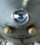
To add
good looking colored IR nose (blue color), I put a small plate inside the nose
and cut a round type missile head of some unused kit (to imitate IR camera
lens) and luckily in the right size to be put inside the nose and painted Tamiya
clear blue (this is done at the last stage before putting the clear nose).
I
also put a small pitot tube inside the left side of air intake.
Oh one more thing rather than carrying a life missile, I modified the
sidewinder to be the practice mode often carried by the RAF Navy for practice
(though I think I colored it wrong, later part).
Painting
It’s started with
the white color of the air intake and all undercarriage area. (paint the
compressor blade with chrome silver from Model Master (MM), and covered it with
masking tape once it was dried). The air intake area is quite unrealistic as it’s
having all the joints open. Thus I used Tamiya white putty to cover all the
joints. The outer most air intake pieces (with additional air intake cover) is
glued before painting white inside to have seamless cover). Masking the wihite
color air intake with Tamiya tapes leaving the outer most edges for body color (grey)
later on. I put the
masked canopy and glued it firm. All ready for base coat painting. As I don’t
have RAF ref paints. I use the lower grey of Dark ghost gray (MM) and the upper
portion Dark Gull Gray (MM). It looks quite similar to the ref photos that
I’ve got.
Once the base coat was finished, all the decals are applied the fuselage.
As I don’t have
any aftermarket decals for more options, I used the kit’s provided decals. but
not using the fancy color option, instead using minimal decals for operation
mode. So I leave all those celebration markings.
I cannot recreate a round white decal supposed to be in the vertical fin
for this squadron.
After all the decals
was applied, I covered the model with clear spray from a Tamiya can (faster) making all decals
lying flat (also using the Mr. Hobby decal fix solution when applying the decals and
waited for it to dry completely, if not the decals would shrink when clear spray applied
(a horrible experience). After the clear coating, the pastel dark grey slimy solution
(added liquid soap pastel powder) is applied to fill up all the recessed panel
lines. Wiped clean after dry leaving nice panel accents. Rather than putting directly
the flat clear final coat, first I air brushed a neutral gray extra thinned to
even the decal color, the upper and lower grey color, so it’s looked natural
(a bit washed out). Finally a semi flat clear final coating is applied.
For
dirty looks especially in the area of jet exhaust, tail, a bit in air intake
area and bottom part of the plane, I used a thinned flat black (I’m actually
using thinned automotive paints this time to have a quicker drying time). I air brushed
several stained colors to the tail area, bottom area and several air intake areas
to make it look dirty. Also the moveable nozzle is dirtied or accented using
this black flat (of course after it was painted with Alcad jet exhaust for hot exhaust
nozzle and Alcad magnesium color for the front compressed air nozzle).
Final
construction
I put all the
detailing components including undercarriage parts, extra fuel tanks, practice
missile, pitot tubes, transparent parts, etc, into their intended places.
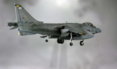
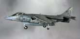
I created
a 3mm steel wire and wooden base to hang the aircraft in hovering mode.
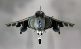
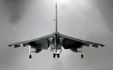
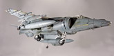
After 2 months (every weekend building) work is complete. Giving lot’s of
satisfaction to complete “The Hovering Harrier”. Please find several pose
(edited with software) to show the hovering acts.
Andy
Click on
images below to see larger images
|

|
|

|
|
|
|
|
|
Photo 7 |
|
Photo 8
|
|
Photo 9 |
|
Photo 10 |
|
|